KORRY Button Tutorial
- Okan Saçlı
- Jan 27, 2019
- 3 min read
Updated: Jan 7, 2021
I've already published a short guide on how I make produce my korry type buttons. There is even a short video on my youtube channel on korry production.
In this tutorial I will give provide more detailed descriptions and steps in the production. The end product will be like below. So please follow the steps provided and better improve on the way.
#airbus #a320 #airbusa320 #homecockpit #homesimulator #simulation #electronics #turkish #engineering #challenge #3d #3dprinting #cockpit #objektifimden #korry #button #construction #design #manufacturing

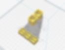
The 3d design was done in AutoCAD environment and exported as a *.stl file. The stl file is opened in Ultimaker CURA software, where is it geocoded for 3d printing.
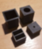
The printed components looks like below. There is an outer casing and inner part for the leds and the engraved label.
I drill 2.5mm holes on the bottom of the korry outer casing piece (there are already holes on them). The idea is to have the power cables to the leds move freely through these holes . I will modify the 3d design so that I do not need to drill additionally.

I then test that the LED power cables run smoothly through these holes.

This is the button I use in my korry setup, this one is a momentary push button, the same size button is also available for latching types if needed for different types of korry.

I install the button on the outer casing piece of the korry as seen below.
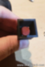
This is what the korry outer casing looks like after the button is installed.

I file the edges of the inner korry part (the part for the leds and the label). This is just to be sure that it runs smoothly inside the outer casing.
After filing just give it a couple of tries to make sure it runs smoothly inside the outer casing. Feel the spring force of the button.

Drill 4 x of hole on the bottom of the inner piece. Make sure you are all the way to the corner. (I will modify the original 3d design so that the stl will produce the 3d part with the holes)
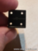
Take 2 x 3mm leds . You’ll bend the legs (both the negative and the positive legs) 90 degrees.

Below, I have a wooden template with holes , where the leds can fit it. Please note that this is a parallel connection of these leds. For serieal connection the leds must be soldered in a different manner. This depends on the voltage supply on your output card.

After soldering is finished, he negative of LED1 and the positive LED2 is cut as seen below. The remaining legs will be shortened and cables will be soldered to them. So basically the black wire is the positive and the white wire is the negative.

This part is a bit tricky , needs some tests and patience. You should now insert the soldered led groups into the inner piece as seen below . Align the leds so that they are centered and perpendicular to the bottom. Below is a close-up of both led groups placed inside the inner casing. Make sure they sit on the bottom, are centered and are perpendicular to the bottom. Then you will the cavity with hot glue. The hot glue should be very fluid to fill the complete cavity, so that the leds and the cables do not move anymore when the hot glue is cooled down. You should pour some additional hot glue (overfill the cavity just a bit) and place the upper label and let some of the glue come out from the sides (we will file them). Make sure you do not burn your hands / fingers here. And also make sure which led group is which color prior to gluing (or you may end up with yellow OFF and WHITE FAULT which is wrong)

I then paint the sides of the clear plexi label to avoid light bleed. I use a typical glass paint for this, below is the painted sides can be seen in a close up.

I then pass the cables from the led block through the bottom holes of the outer casing as seen. Apply a single drop of fast glue in the center of the red button. And then insert the led block piece and press it firmly on the button for the fast glue to fix.

Here is what the finished product looks like.


